Noise Floor Of Spectrum

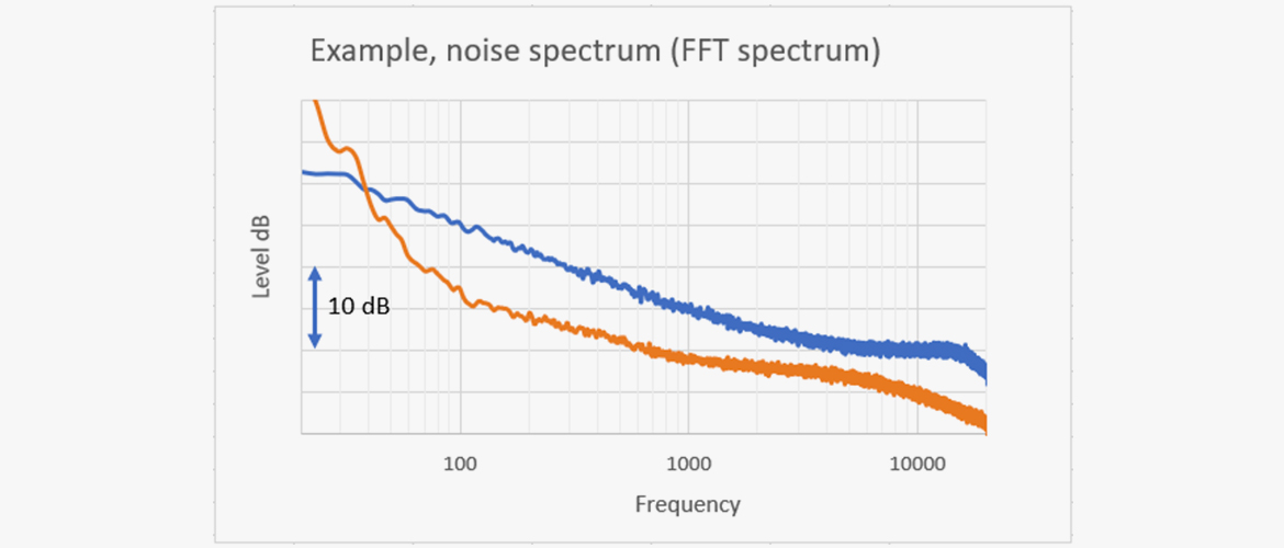
Noise Spectrum An Overview Sciencedirect Topics

Optimization Of Weak Signal Measurement By Spectrum Analyzer Micronix

Effects Of Noise On Sampler Quantization Errors

Pocket Rta Hd Specrum Analyzer For Ipad 6th Octave Display Plus Capture Http Www 4pocketsaudio Com Product Php P 5 Spectrum Analyzer Audio Equipment Ipad

Brownian Noise Wikipedia

Influence Of Noise Processes On Jitter And Phase Noise Measurements 2018 03 29 Signal Integrity Journal

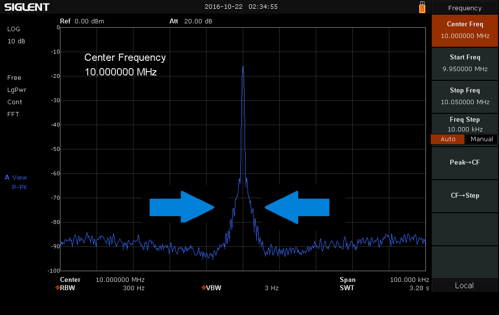
Measurement from a spectrum analyzer showing the noise floor.
Noise floor of spectrum. Spectrum display window if your red dots don t line up with signals adjust the noise floor then use shift up down to jump from signal to signal. As this will typically be an amplifier its noise level is likely to be greater. Then the dut is connected and its signal captured and saved to trace 2. In signal theory the noise floor is the measure of the signal created from the sum of all the noise sources and unwanted signals within a measurement system where noise is defined as any signal other than the one being monitored.
A spectrum analyzer s ability to measure low level signals is limited by the noise generated inside the spectrum analyzer. If not a further low noise amplifier can be added after the device under test to bring the noise. If for example we wanted to determine the noise floor from 0 to 1 ghz would it be best to run a sweep using a full 1 ghz span or would it be better to pick various frequency ranges with smaller spans. This equates to a 3 db decrease in the rms noise level.
Trace math is then used for a power subtraction of the two traces with the results saved to trace 3. Thus the apparent noise floor of the spectrum depends on the bin width or δf which in turn is a function of the number of fft bins. To make the noise figure measurements required the spectrum analyzer should have a noise floor that is 6db lower than the noise emanating from the device under test. This sensitivity to low level signals is affected by the analyzer settings.
Figure 9 for example depicts 50 mhz signal that appears to be shrouded by the analyzer s noise floor. The spectrum display window. 6 3 spectrum analyzer display over a 10 mhz frequency band centered on 1 ghz. The total power in the resolution bandwidth at each frequency point.
Each time you double the number of fft bins the bin width is halved reducing the noise power in each bin by a factor of 2. With a spectrum analyzer what is a good method for determining the local noise floor in the lab area around the spectrum analyzer. The noise floor of the spectrum analyzer is first averaged with the input terminated with these results saved to trace 1. If you are having trouble finding a cq frequency press the cq button.
The reference level is set to 70 dbm with a noise marker set to the center frequency diamond shape partially hidden by the noise spectra at center.
Spectrum Analyzer Basics Bandwidth Siglent

Understanding Rf Microwave Specifications Part I National Instruments
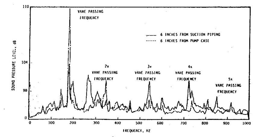
Noise Spectrum Of Cavitation 4 0 Diagnosis Of Noise And Vibrations In Download Scientific Diagram

Spectrum Analyzer Sa9115 Series Spectrumanalyzer 160dbm Display Average Noise Level Min 100 Dbc Hz 10 Khz O Spectrum Analyzer Spectrum Wellness Design

Sponsored Vintage Teac Eqa 190 Stereo 10 Band Graphics Equalizer W Spectrum Display In 2020 Vintage Electronics Teac Stereo
Microphone Noise The Basics About Self Noise In Mics

Fft Scaling For Noise Audio Precision

Spectrum Analyzer Software Market Measures Up In 2020 Spectrum Analyzer Wireless Transmitters Wireless Transmitter

Noise Spectral Density A New Adc Metric Analog Devices
Rosewill Spectra C100 Atx Mid Tower Computer Pc Gaming Case Full Tour Noise Level Check Youtube Computer Tower Pc Computer Atx

The Differences Between Dynamic Range Signal To Noise Ratio Pro Sound Web Dynamic Range Signal To Noise Ratio Noise

Rethinking Marine Acoustic Ecology Research Is It Time For A Change Sound Science Electromagnetic Spectrum Rethought

12 Mm Mdf Acoustic Ceiling And Wall Boards Soundproof Perforated Wall Panels Acoustic Panels Wall Panels Paneling

